Electronics don’t “just get assembled.” A reliable device is the result of a tightly controlled chain of decisions—design rules, sourcing, PCB build, mechanical integration, testing, quality control, packaging, and fulfillment.
If any step is rushed, you’ll feel it later as rework, failures in the field, missed ship dates, and ballooning costs.
This guide breaks down a practical, end-to-end electronic manufacturing process in 10 steps—and highlights where precision metal fabrication (enclosures, chassis, brackets, heat sinks, tooling/fixtures, and pack-out) fits into the workflow.
What is electronics manufacturing?
Electronics manufacturing is the process of turning an engineered design (electrical + mechanical) into a repeatable, shippable product.
From design intent to production reality
It typically includes design-for-manufacturing checks, sourcing, PCB fabrication and assembly, mechanical fabrication for housings and mounting hardware, integration or box build, test, inspection, packaging, and distribution.
Depending on your product, your supply chain may involve multiple partners. The fastest programs reduce handoffs by aligning documentation, tolerances, and build responsibilities up front.
Where precision metal fabrication fits into electronics manufacturing
Even “electronic” products rely on mechanical parts to survive the real world.
Why metal components matter
Metal components often determine heat dissipation, EMI and EMC shielding performance, rigidity, connector alignment, and serviceability.
Common metal deliverables in electronics builds include enclosures and chassis, brackets and mounting panels, heat sinks and thermal plates, covers and shields, and precision tooling or fixtures.
For teams looking to reduce supplier handoffs, partners like Eagle Metalcraft support electronics programs with integrated precision sheet metal fabrication, CNC machining, and fabrication assembly services.
10 main steps in the electronic manufacturing process
Most successful programs run these steps with overlap rather than strictly linearly, but the sequence below reflects how teams prevent avoidable rework.
Step 1: DFM and DFX review
Before anyone buys parts or cuts metal, manufacturability must be validated across both electrical and mechanical domains.
This includes electrical DFM considerations like pad sizing, spacing, soldering approach, and test access, as well as mechanical DFM elements such as bends, fasteners, tolerances, datum strategy, airflow, and service access.
The outcome should be a buildable revision with clear drawings, controlled tolerances, and an inspection plan that reflects real risk. Guidance from organizations like NIST MEP reinforces the importance of early manufacturability alignment.
Step 2: Sourcing and BOM control
Your bill of materials is the single source of truth—until revisions drift.
Strong sourcing focuses on approved alternates, lead-time risk mapping, and strict version control so BOM revisions match CAD and drawing revisions.
For metal components, this is where material specifications, finishes, hardware, labeling, and packaging requirements are locked to avoid downstream surprises.
Step 3: PCB fabrication and PCB assembly
This is the electronics core of the build.
Whether PCB fabrication and assembly are internal or managed by an EMS partner, the mechanical design must respect the assembled board.
Keep-out zones, connector alignment, mounting hole strategy, standoff heights, and thermal interfaces all influence long-term reliability.
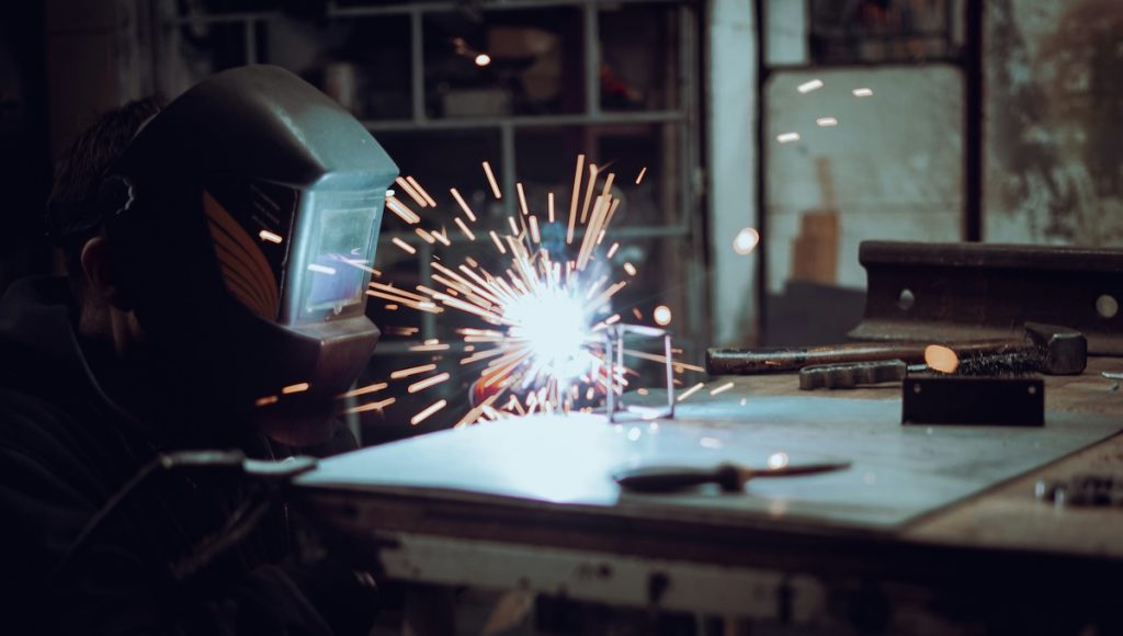
Step 4: Metal fabrication for enclosures and structural parts
This step is where the device becomes a product instead of a board on a bench.
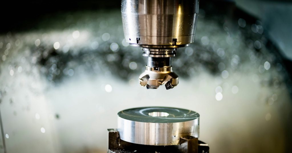
Typical workflows include laser cutting or punching, forming, welding where required, CNC machining for tight-tolerance features, hardware insertion, and surface finishing.
Key success factors include controlled flatness for gasket compression, consistent hole-to-hole location for connector alignment, and predictable thermal interfaces.
Step 5: Sub-assembly and hardware insertion
Before final integration, many programs assemble modules such as fan trays, mounting panels with PEM hardware, or bracketed subframes.
Catching issues at this stage prevents late-stage rework caused by incorrect standoff heights, missing hardware, or poor access.
Step 6: Final assembly and box build
Box build integrates boards, cables, and mechanical components into a complete unit.
A controlled process includes documented work instructions, grounding and bonding plans, cable routing standards, and revision-controlled labeling.
Done right, this step prevents failures caused by connector stress, loose fasteners, or inconsistent grounding. Safety and grounding practices should align with expectations outlined by OSHA.
Step 7: Firmware loading and configuration
Some products require firmware programming, configuration, or calibration.
This step must be version-controlled and traceable so each serialized unit can be tied back to the exact software and configuration shipped.
Step 8: Functional testing and verification
Testing should reflect how the product will actually be used in the field.
Mechanical design directly affects testability through access points, fixture compatibility, and stable mounting during test.
Step 9: Outgoing quality control and traceability
Outgoing quality control ensures the right product ships in the right quantity with the correct documentation.
For higher-reliability or regulated programs, traceability is essential for containing issues and avoiding costly recalls.
Step 10: Packaging and distribution
Packaging is part of manufacturing, not an afterthought.
Electronics packaging often must address shock, vibration, moisture, ESD protection, labeling, and shipping documentation to ensure products arrive intact and traceable.
Tips to reduce delays and defects in electronics builds
Small process upgrades consistently create large schedule and quality wins.
High-impact practices
- Lock revision control between CAD, drawings, and BOM
- Design mounting and grounding intentionally
- Use datums that reflect real assembly conditions
- Maintain service access for rework and maintenance
- Treat packaging as an engineered system
How Eagle Metalcraft supports electronics and semiconductor programs
Eagle Metalcraft supports the mechanical and integration side of electronics manufacturing, including precision sheet metal fabrication, CNC machining for tight-tolerance interfaces, and fabrication assembly for hardware insertion, labeling, and pack-out.
This approach helps electronics and semiconductor programs reduce supplier count, control revisions, and move more smoothly from prototype to production.
Get a quote
If you want a faster, cleaner path from prototype to production—especially for enclosures, chassis, brackets, thermal parts, and assembly—send your drawings and BOM details through the request a quote page or reach out via the contact form.
FAQ
Electronics manufacturing has many moving parts.
Do I need separate vendors for PCB assembly and metal enclosures?
Not always, but mechanical vendors should be aligned early so enclosure interfaces do not create late-stage rework.
What should I send to get an accurate enclosure or chassis quote?
STEP file and PDF drawing with datums and tolerances, material and finish requirements, hardware requirements, assembly expectations, and quantity by build stage.
What are the most common enclosure mistakes that hurt electronics reliability?
Poor connector alignment, insufficient grounding, bad thermal interfaces, hidden fasteners, and no cable strain relief plan.
Can you support sub-assemblies and box build-style integration?
Yes. Fabrication assembly programs typically cover hardware insertion, labeling and serialization support, and pack-out.
Do you support semiconductor-related tooling and fixtures?
Yes. CNC machining and precision fabrication are commonly for semiconductor tooling, fixtures, and related components.